How to install an NTP
What is an NTP?
An NTP (=network termination point, demarcation point) is the point at which the Proximus network ends and connects with the customer’s internal cabling. It is the dividing line between Proximus and customer’s domains.
What does an NTP look like?
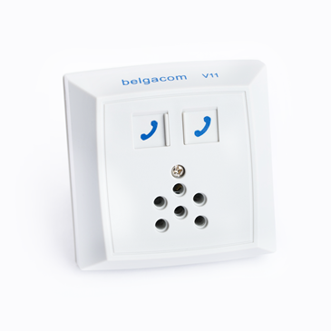
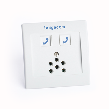
A modern NTP should be a TF2007 connection box and look like this:
 |
 |
| a built-up NTP | a built-in NTP |
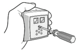
1. Remove the old connection box (at the point where the Proximus network comes into the house/apartment).
2. Open the TF2007.
 |
3. Unclamp the central block.
 |
4. Open the white flap.
 |
5. Poke through the holes in the baseplate which you are going to use for screws when mounting the TF2007.
 |
6. Close the white flap.
 |
7. Make an opening for the cable in the baseplate.
 |
8. Make an opening for the cable in the case of TF2007.
 |
9. Decide where you want to place your NTP and place the baseplate onto the wall in that place.
 |
10. Clamp the central block back onto the baseplate.
 |
11. Fasten the baseplate of TF2007.
 |
12. Connect the wires with the connectors.
- Loosen the screws by turning them counterclockwise.
- Put the wires into the corresponding connector.
- The orange connector is used for grounding (mostly, not connected).
- The two network wires with a tone should be put into the black connector.
- All wires for telephony, including alarms and other accessories, are put into the green connector.
- In case you are using a separate cable meant only for connecting the modem/router, put it into the blue connector.
- Tighten the screws by turning them clockwise.
 |
13. Close the TF2007.
 |
1. Open the TF2007.
 |
2. Unclamp the central block.
 |
3. Open the white flap.
 |
4. Make an opening in the upper or lower side of the baseplate depending on where the wires go through.
 |
5. Poke through the holes in the baseplate which you are going to use when mounting the TF2007 and pull the wires out.
 |
6. Take the fastening clamp for a built-in box.
 |
7. Loosen the screws so that the parts of the fastening clamp come apart.
 |
8. Stick the double-sided duct tape to the corresponding part of the fastening clamp.
 |
9. Stick the bottom of the clamp holder to the back side of the baseplate.
 |
10. Tighten the screws.
 |
11. Attach the clamps to the clamp holder and slightly tighten the nuts.
 |
12. Place the rubber band over the clamps.
 |
13. Pass the wires through the opening in the baseplate and place the baseplate on the wall.
 |
14. Screw down the baseplate.
 |
15. Close the white flap.
 |
16. Clamp the central block back onto the baseplate.
 |
17. Connect the wires with the connectors.
- Loosen the screws by turning them counterclockwise.
- Put the wires into the corresponding connector.
- The orange connector is used for grounding (mostly, not connected).
- The two network wires with a tone should be put into the black connector.
- All wires for telephony, including alarms and other accessories, are put into the green connector.
- In case you are using a separate cable meant only for connecting the modem/router, put it into the blue connector.
- Tighten the screws by turning them clockwise.
 |
18. Close the TF2007.
 |
